
At a meeting with the Law Courts Committee in April 1841, Elmes requested that Dr David Boswell Reid of Edinburgh should be appointed as 'Ventilator' for St. George's Hall. Reid had designed a very successful system for the Temporary House of Commons, which had been hastily erected in 1835 following the disastrous fire of October 1834. Reid had delivered many lectures on the subject of ventilation while he was in London and Elmes is likely to have attended some of these.
In 1844 Reid published a 350-page book Illustrations on the Theory and Practice of Ventilation and the frontispiece of this carries a sketch of St George's Hall with the proposed Daily Courts Building closing off the North end of the public forum. What is striking about this is the fact that at the rear of the Daily Courts Building is a 'Tower of Wind' about 200 feet (60m) high, which was to provide ventilation exhaust and chimney exhaust for both buildings. This involved all extract air and all chimney exhausts in St George's Hall being taken down into the basement and then through tunnels under Shaw's Brow (now William Brown Street) before passing up through this tower. A furnace would have been burned at the base of this tower to provide the necessary updraft, this was similar to the system employed in the Temporary House of Commons. A perspective sketch by Elmes shows the Daily Courts Building surmounted by a massive dome as an alternative, very similar in appearance to the dome on the Capitol in Washington, which was not built until at least 10 years later.
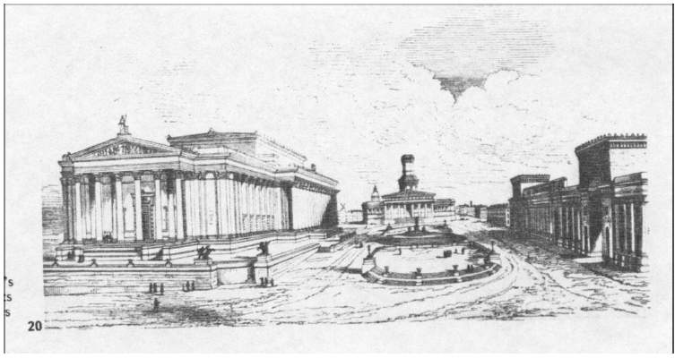
Elmes' Perspective Showing Wind Tower Behind Daily Courts Building. (Shown on the right is John Foster Senior's facade to Lime Street Station)
The fact that Elmes requested Reid's appointment as early as 1841 and that the above sketch appears in Reid's book of 1844 discounts the suggestion of some writers that the building was originally designed without a ventilation system and that this was 'added' on the recommendation of Dr William Henry Duncan, the City's Medical Officer of Health. Duncan was not appointed to that post until January 1847.
Elmes early diagrams clearly show all fireplace chimneys turning downwards and much of the basic building work on St George's Hall had been done (in fact the principal floor level had been reached) when the plan to build the Daily Courts was abandoned and it is much to the credit of Elmes and Reid and to the cooperation between them, that the ventilation system in the finished building worked so effectively. However, Reid points out in his 'Building Handbook' that this late change in arrangements caused some difficulty with the provision of an adequate and controllable supply of air to some of the ancillary rooms, such as the Barristers' Library and the Vice-Chancellor's Court.
Reid's System and its Operation
All of the features Reid had outlined in his book as essential for the successful application of 'systematic ventilation' were incorporated into the warming (or cooling) and ventilation arrangements for the principal spaces. The main driving force was a 10 hp (12kW) steam engine driving four vast paddle fans 10ft (3m) in diameter, with blades 5ft (1.5m) by 2ft 6in. (0.75m). By varying the speed of the steam engine and changing the number of fans operating at any one time, the air supply rate could be varied from 1 000 ft3/min to 50 000 ft3/min (0.5m3/s to 25m3/s).
The two main fresh-air intakes are on the East side of the building at either end of the East portico. At that time St John's Church (and, more importantly, its graveyard) were still adjacent to the west side of the building and so Reid was desperate to avoid the possibility of smells from the graveyard permeating into the building or coming in through the intakes of his ventilation system. Fountains operated under these main air intakes to 'wash' the air (in fact, although Reid had made provision for these two fountains, they were not installed until a few years later) and the air then passed through the vast undercroft before reaching the steam engine and fans. Reid was well aware of the temperature moderating influence of this labyrinth of masonry, was this, perhaps, its main function?
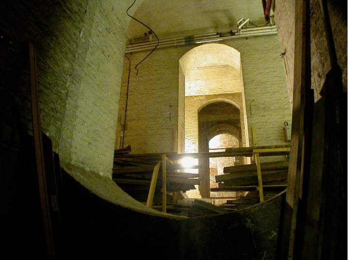
The undercroft is about 40ft (13m) high.
The air was heated by means of two hot water boilers and two steam boilers, all fuelled by coke — Reid was very conscious of the health problems associated with chimney smoke in cities. The two main heating coils (the Great North and the Great South Water Apparatus) consisted of 72 x 4in. (100mm) steel pipes about 30ft (10m) long. There are two smaller coils for heating the Small Concert Room and the North Entrance Hall and one for the South Entrance Hall. This latter coil is now part of the display in the new Heritage Centre opened in 2007. In addition there were 27 pipe coils heated by the steam boilers. In very hot weather cold water from the Town Main could be passed through the heating coils to provide cooling and then discharged into the drain.
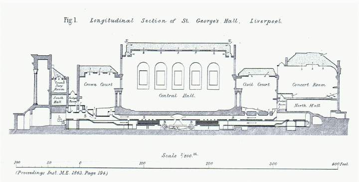
Reid's diagrams. Left:
Longitudinal Section of St. George's Hall, Liverpool. Right:
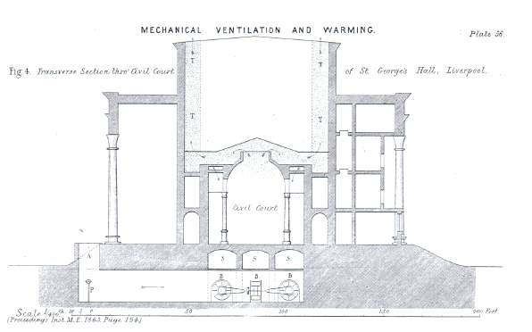
Mechanical Venilation
and Warming: Transverse Section thro' Civil Court of of St. George's Hall, Liverpool.


Left: Part Section from Reid's Instructions
Top right: Basement Plan of St. George's Hall, Liverpool, at level of Upper Air Channels. Bottom right:
Basement Plan of St. George's Hall, Liverpool, at level of Lower Air Channels
The diagrams above have been taken originally from Reid's instruction manual given to Liverpool Council in 1855. These copies are from reproductions in a paper by William McKenzie, the first engineer employed to be in charge of the operational control of the system. The paper was delivered to the Institution of Mechanical Engineers in the Small Concert Room in 1863.

Main Air Intake at North End of East Portico
The steam coils were only to be used in extremely cold weather because of Reid's belief that heating the supply air to a very high temperature was detrimental to comfort. However, in winter, the steam coils would be employed for pre-occupancy warm-up. This was effected by closing all the normal escape routes for vitiated air and re-circulating the air to the fan chamber by allowing the flow to be reversed through the low-level supply grilles in the Great Hall. Humidification was obtained by direct injection of steam into the air stream under the main heating coils. Reid insisted that this steam must come from a separate boiler used solely for that purpose and that only copper pipes were to be used in association with it.
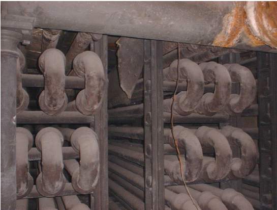
Left: Main Air Intake at North End of East Portico. Right: Great North Water Apparatus (Pipes are 100mm in Diameter).
A complicated system of ducts and 'valves' allowed treated air to be sent to any combination of the principal spaces or where a very rapid warm-up was required, all four fans could be made to operate on a single space. The 'valves' in this case are large doors of sized canvas over a timber frame. Wooden louvre dampers and canvas roller blinds were used for finetuning.
Supply from the main system into all the principal rooms is at low level but the system allowed supplementary (untreated) fresh air to be introduced directly as required. Vitiated air was encouraged to escape from the Great Hall into the roof space, the roof having louvres round all four sides (but below the parapet). Extract grilles, with openable flaps above, were skilfully incorporated into the ceiling decoration. The roof louvres were controlled so that only those facing away from the wind direction would be opened.
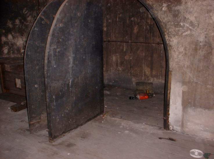

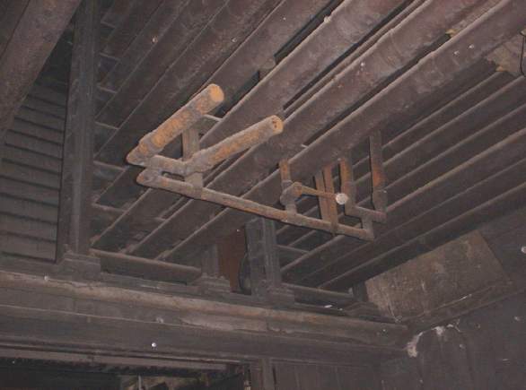
Left: Typical 'Air Valves' these are about 6ft (1.8m) high. Right: Position of Gas Jet in Extract Shaft.
All other principal rooms and many of the ancillary spaces had their air extracted into four main vertical extract shafts, one next to each corner of the Great Hall. Each of these also contained a boiler flue. Fish-tail gas jets could be burned at the bottom of these, or in one case, a coke brazier, to boost the buoyancy of the air and increase the extract rate. Chimney flues from those rooms with fireplaces, were fed into a separate vertical flue alongside these shafts and again, when necessary, a coke brazier or gas jet could be ignited at the bottom of these vertical flues.
The rate of extract from the Court Rooms could be closely controlled by adjusting flaps in the roof space. For the two Courts and the Small Concert Room it was possible, in warm weather, to allow vitiated air to escape directly out of the roof space.

Roof Space Over Court No 2 (Originally Civil Court).
Reid provided extremely comprehensive instructions for the successful operation of the system. These run to about 12 pages, approximately A2, and include almost 50 diagrams of the necessary arrangements. They are a veritable 'Building Handbook**' and must say something about Reid's pride and satisfaction in the building since there was no equivalent publication for Parliament. They include reference to the importance of regular (and recorded) maintenance, guidelines on the most economic modes of operation for different occupational requirements, hints on how to make maximum advantage of the thermal capacity of the vaults under the Great Hall and a recommendation that a log be kept of the settings required to provide equitable conditions for different numbers and patterns of occupancy.
Reid even gave a detailed specification of the person who should be put in charge of ensuring the correct operation for optimum comfort and energy efficiency. He said:
Those who may in future have to direct the ventilation of this great building, are presumed to have given evidence of their having paid special attention to the subject of ventilation; and the more they may have attended questions of practical chemistry bearing on warming and ventilation, as well as to natural philosophy, architecture, apparatus and machinery, the more eligible they must be considered for the appointment in question.
The first person to be appointed to operate Reid's systems was William MacKenzie, a member of the Institution of Mechanical Engineers. MacKenzie delivered a Paper to the members of that Institution in the Small Concert Room of St George's Hall in 1864, where he described the system in detail and gave an account of how successfully it had operated. This Paper discusses Reid's instructions and diagrams and acknowledges the reproduction of the diagrams, even using the same numbers as Reid. The same may not be said for Charles Honiball whose paper in the Proceedings of The Institution of Heating & Ventilating Engineers in 1907 is blatantly plagiarised from MacKenzie's paper and in which Reid's diagrams are renumbered and presented as if they were Honiball's own!
Bibliography
MacKenzie, W. 1863. "On the Mechanical Ventilation and Warming of St George's Hall, Liverpool", Proceedings I Mechanical Engineering (1863): 194-208.
Reid, David Boswell. "Diagrams of the Ventilation of St George's Hall and the New Assize Courts, Liverpool." 1855. Manuscript in Liverpool City Record Office.
Reid, David Boswell. Illustrations of the Theory and Practice of Ventilation. London: Longmans, 1844.
Last modified 24 March 2013